FLL Field Mapping Studio helps you plan where the robot should start, move, turn, pause, and finish on the field. It is not trying to predict every real-world detail. It gives students a shared picture of the route before they test it on the mat.
Use the Training area first if the field coordinates, headings, or turn-center offset are new ideas. Use the Mission Tool when you are ready to sketch an actual route.
The main page is where you build a route. Start by connecting your team if you want to load or save cloud missions. Then set the mission name, starting X/Y position, starting heading, robot size, robot color, and attachments.
Mission actions are read from top to bottom. A move goes forward or backward in centimeters. A rotate turns by degrees in Relative Mode or turns to a field heading in Global Mode. A pause marks the robot working in place for a number of seconds and leaves a purple outline on the field.
The trace color controls the path line. The robot color controls the robot body and attachments. The replay controls let you scrub through the route right away, so you can check the route one frame at a time.
Training lessons are short practice pages separate from the Mission Tool. Each lesson has instructions on the left and a focused sandbox on the right. They are meant for students who are learning the field map, not for scoring or grading.
Lessons cover field orientation, movement, rotation, pause blocks, robot placement, base robot size, turn-center offset, and attachments. The offset lesson is especially useful because it shows how the same route changes when the robot turns around a different point.
Robot Builder is for making a reusable robot profile. Set the base size, color, turn-center offset, and attachments, then save it locally, stage it for the Mission Tool, or save it to your team cloud.
The red mark shows the front of the robot. The purple crosshair shows the point the robot rotates around. If your robot does not turn around its exact center, changing this offset makes the planned path more realistic.
Distances are centimeters and angles are degrees. The lower-left corner of the field remains the X/Y coordinate origin in both heading modes.
Relative Mode uses the original field angles: 0 points right and 90 points up. Each Rotate value is an amount added to the robot's current angle, so negative values turn clockwise.
Global Mode uses fixed headings based on the field: 0 points upfield, 90 points right, -90 points left, and 180 points downfield. The starting heading uses this system, and each Rotate value is the heading the robot should face next. The curved arrow on each Rotate block shows the turn direction. The planner chooses the shortest turn by default; select the arrow to use the opposite path. An exact 180-degree turn defaults to clockwise.
The planner does not model wheel slip, acceleration, sensors, or collisions. If a route only works with a perfect start, use that as a warning sign and design a better alignment or recovery step.
The purple crosshair marks the point used for rotations. A different offset changes where the robot body moves during a turn.
The diagram shows Relative Mode. Use the table to translate the same physical directions into Global Mode.
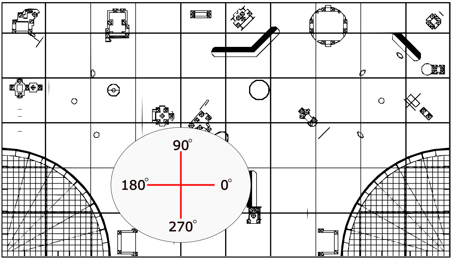
| Direction | Relative | Global |
|---|---|---|
| Upfield | 90° | 0° |
| Right | 0° / 360° | 90° |
| Left | 180° | -90° |
| Downfield | 270° | 180° |